Rotational Encoder from old CD motor

Last updated: September 22, 2010
The spindle motors used in CD-ROM drives often (always?) contain 3 Hall-sensors. These sensors are used by the motor controller to determine the position of the axle. This makes it possible to use these motors as rotational encoders.

Test setup without microcontroller
Test setup with microcontroller,
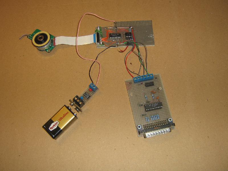
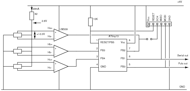
small power supply and programmer


First try to find the connections between the Hall sensors and the motor controller. The datasheet of the motorcontroller is a big help here. The CD-rom used for this experiment used a Toshiba TA8493 motorcontroller. You will probably find something like this:


The Hall sensors are connected in parallel. The Hall-signals are fed into 3 comparators. The current through the sensors is limited by 2 resistors. One of these resistors is connected to Vcc (5V), the other is connected to the motorcontroller. This is probably used to switch the current through the sensors on and off.

By feeding the Hall signals into a LM339 you get 3 TTL compatible signals that indicate the axle position.


The Hall sensors are permanently connected to Vcc and GND. Because the common mode range of the LM339 includes ground only 1 current limiting resistor is needed. The common mode voltage of the sensors is approx. 1.3V, the differential Hall voltage is approx. 0.3V.

Rotating the motor gives the following output pattern: 001, 000, 010, 110, 110, 101. The pattern depends on how the LM339 signals are connected to the hardware, so YMMV. The test setup gave 36 changes per revolution.
This is not compatible with the usual encoders which have 2 output signals. There are several ways to handle this:

With microcontroller

An attempt to interface the encoder directly to 3 ADC channels of an ATtiny13 microcontroller failed. Probably due to the following reasons: The Archive contains the ADC code (oenc_adc.c)

In a second attempt the outputs of the (already existing) LM339 where connected to the ATtiny13.

After the required code change, this worked at first try.
The internal pull-up resistors of the ATtiny are enabled. The code uses a timer interrupt to generate the serial output, and the 'pin changed' interrupt to detect rotor movements.

The ATtiny13 generates 2 output signals: a RS232-like signal on pin 6 and a pulse to signal a change on pin 5. When turned anti-clockwise the ATtiny generate a 'B' (0x42) on pin 5 and a positive pulse on pin 6 during the time pin 5 is low. When turned clock-wise a '<' (0x3c) is generated and pin 6 is high during the pulse on pin 5:

AVR programming

I used an improved STK200 programmer (local copy), connected to a FreeBSD 8 system with avrdude, for this project. See the archive for the AVR code.

To change the internal clock from 1.2 MHz to 9.6 MHz the CKDIV8 bit in the Fuse Low Byte has to be set to 1. The avrdude command for this is
	avrdude -v -P /dev/ppi0 -c stk200 -p t13 -U lfuse:w:0x7a:m
This has to be done only once.

The software is programmed with
	avrdude -v -P /dev/ppi0 -c stk200 -p t13 -U flash:w:oenc.bin:r

TODO

Archive containing the Xcircuit files (encapsulated postscript), a DOS test program for the version without the AVR and the ATtiny13 code.