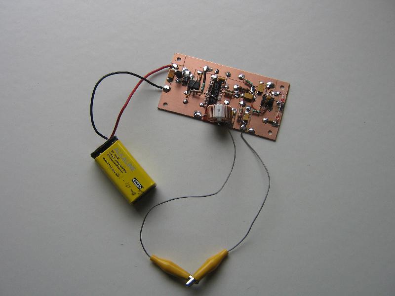
For the repair of a thermal printer I needed an ESR meter
to select some low-esr capacitors from the junk box.
After seeing several designs on the Internet I decided to modify
this design
(local copy of circuit)
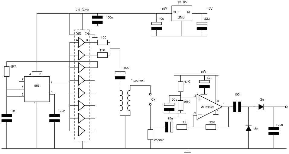
The modifications are a 555 based oscillator with buffer and a
transformer from the junk box.
Oscillator
Without the 74HC245 buffer the 555 does not give a clean output
signal when loaded with the transformer. A single HC245 buffer is enough to
drive the transformer with a clean signal, but I used 2 just to be on the save
side.
The output of the (bipolar) 555 swings to GND, but not to the supply rail.
If the
4K7 feedback resistor is connected directly to the output (pin 3) the resulting
square wave has a duty cycle of approx. 30%. Inserting a HC245 buffer
gives a duty cycle of 50%.
Transformer "design"
The original design
uses a pair of EA-77 E-cores, which were not available. I used the following
parameters to select something from the junk box:
Output voltage: 100 mVtt, primary voltage 5 Vtt ==> n = 50
Rule of thumb: primary reactance should be at least 5 times input resitance => Xl should be 25 - 250 Kohm @ 100Khz
==> Xl (primary) 40 - 400 mH
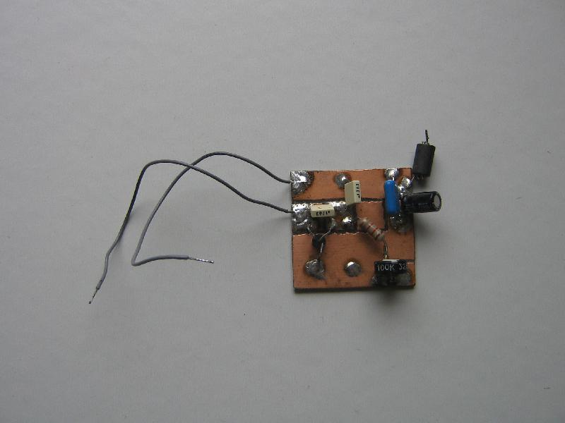
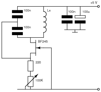
Use this LC meter
to measure inductance or build this simple
oscillator (from "Sinus-, Rechteck- und Impuls generatoren, Lothar Sabrowski, 1971") to check the available coils:
A coil of 40 - 400 mH should give a frequency of 1000 - 3600 Hz.
I used a coil from a mains filter with both windings in series. This coil
oscillated around 9800 Hz, which means an inductance of 5.3 mH.
This is lower than calculated, but it works well.
The secondary winding is a single turn through the coil.
Remark: The core used in the original design has an Al value of
1290mH/1000 turns.
With 400 windings this gives an inductance of 206 mH.
Amplifier design
The op-amp is not critical, but it should work with a single 5V supply,
have a reasonable gain-bandwidth product and
care should be takes to keep it in its lineair region.
With a single 5V supply the MC33072s output swings between 0.3 and 3.7 V
(Motorola datasheet): 3.4 Vtt. With a maximum input of 100 mVtt the
maximum gain is 34. Gain is set to 22.
With the non-inverting input of the op-amp set to 2.26 V, the output swings
between 1.1 Vand 3.4 V with an input of 100 mVtt (test leads shorted).
The MC33072 has an gain-bandwidth product of 4.5Mhz and a slew-rate
of 13V/us. With a square wave input of 100KHz the output signal is visibly
rounded, but this has no impact.
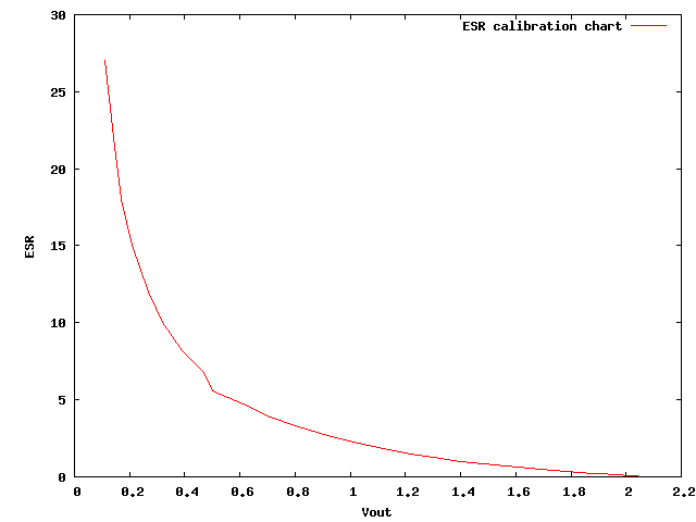
Calibration
Calibrating is done with a number of small resistors. For occasional use
a separate (digital) meter and a calibration chart will do:
R
Vout
R
Vout
0
2.07
3.9
0.71
0.18
1.91
4.7
0.61
0.22
1.88
5.6
0.50
0.5
1.69
6.8
0.47
1
1.40
8.2
0.39
1.2
1.33
10.0
0.32
1.5
1.22
12.0
0.27
1.8
1.12
15.0
0.21
2.2
1.03 *
18.0
0.17
2.7
0.92
22.0
0.14
3.3
0.80
27.0
0.11
*: Half scale, indicating lineair operation.
TODO
Add meter
Add enclosure
Downloads
Archive containing the Xcircuit files (encapsulated postscript) and small tools.